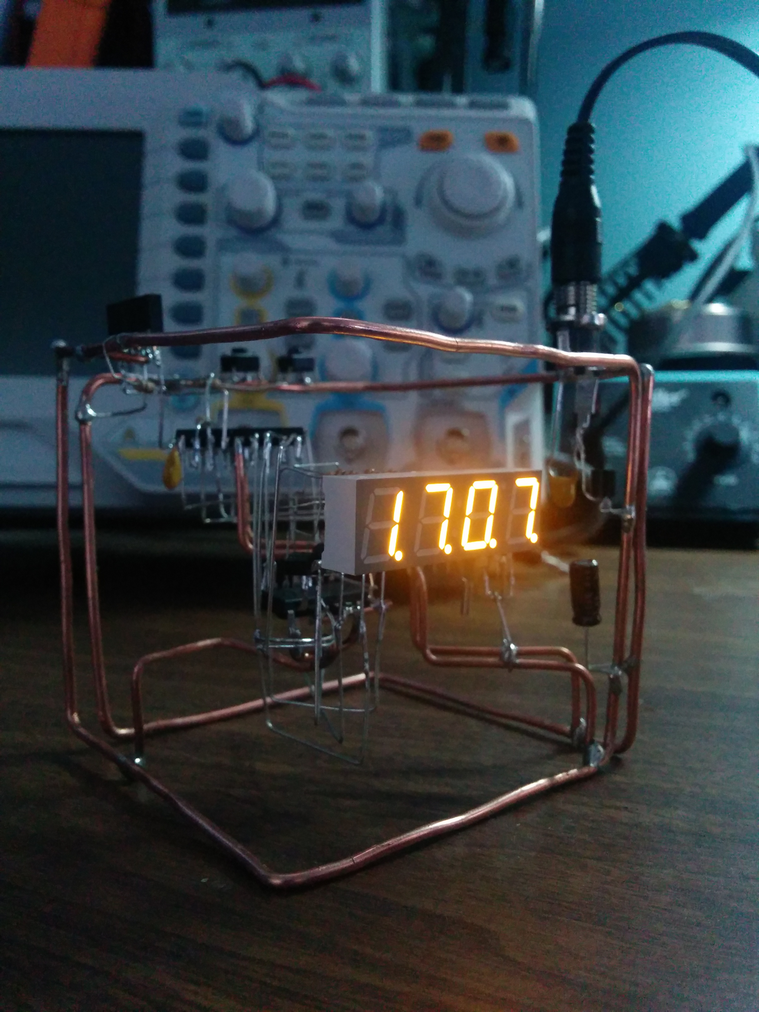
 While I was working on my clock project, I had the idea of creating a clock cube that would be encased in epoxy resin. Not only would it be functional, but it would look cool as you would be able to see the innards of the clock.
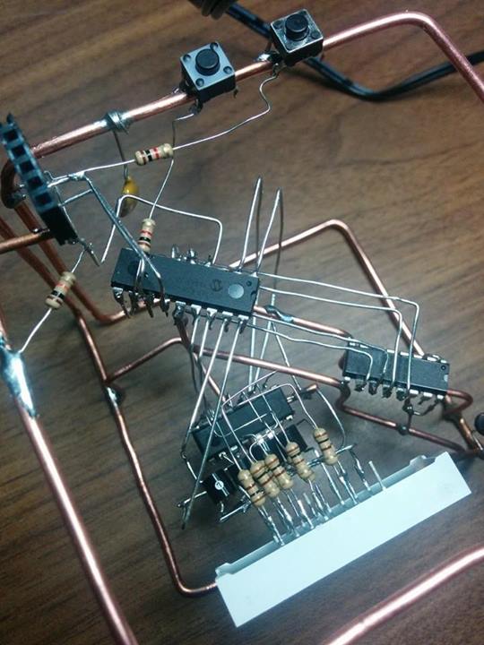
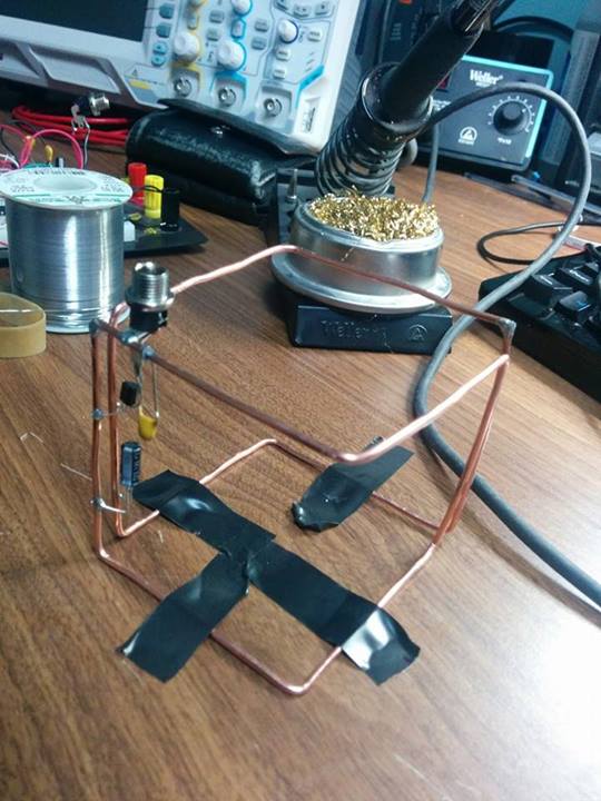
As I worked on the skeleton of the clock, I noticed that it looked similar to something that you would see in a Jim Williams datasheet! I decided to continue the project under that motif.
I have yet to encase the clock in epoxy resin, as I am afraid that it won’t go well. Putting the clock together took a day and a half of work, and I wouldn’t want that to go to waste. I will hopefully get a chance to test some resin casts on small items sometime soon.

A few notable bugs I had in my design (For those of you that like thinking about such things):
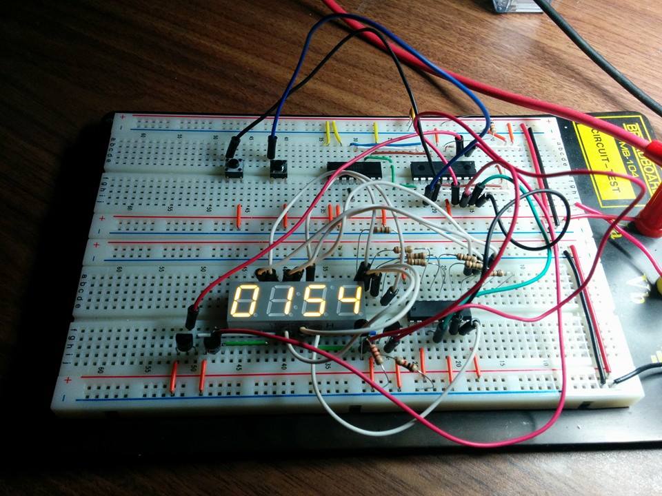
1) I was having issues with the microcontroller resetting when it displayed certain digits on the 7-segment displays. Ends up I had forgot to turn off brown out protection on the uC, and the current draw from the LED’s was pushing the main voltage below the default brown out level for the uC. This was easily remedied by adding some bulk capacitors and turning off brown out protection (not too important for this stripped down clock).
2) One of the last things I did whilst developing the hardware was adding in the stand alone power supply. I opted into using a simple LDO and a wall wart. I wired everything up on my breadboard, and it all seemed to be happy. Once I unplugged my scope probe though, trouble arrived. Whenever I pressed a button to change the time, the whole clock would reset. This issue arose since I had been lazy with my output capacitors on the LDO. I neglected the fact that there needs to be a certain ESR on the capacitors for the LDO to operate stably. What threw me for a loop was the fact that the clock worked perfectly, and the power rails looked great when I was probing it. I didn’t realize until after reading the datasheet on the LDO and asking some friends, that I had the LDO driving a nearly complete capacitive load, and it was becoming unstable whenever any meaningful current was drawn. Easily fixed by replacing the ceramic output capacitors with an electrolytic cap that had the required ESR for the LDO.
3) I was running into flash space issues with my code. I had created a interrupt that would run when the button was pressed, and the interrupt would update the time nicely as long as the button for it was held down. When I tried to compile this code, the XC16 compiler complained of too many nested if statements, and too little program memory; oops. I forgot about how compilers tend to unwrap while loops and if statements, which ended up taking most of my program space. I was able to circumvent this by simply having one complete button press as one increment of either the minutes or hours (depending on which button was pressed).

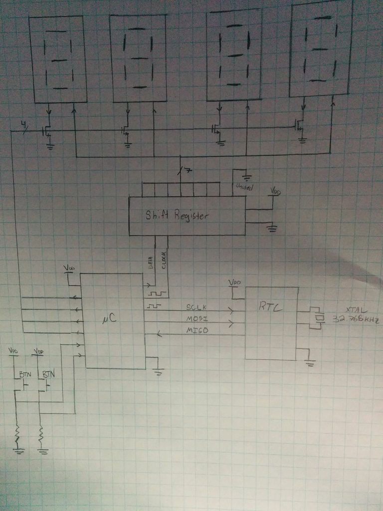
I have a partial schematic of the clock, which I will try to finish up to add to this post. In the meantime, I have some images of the clock operating, which shows off the (partially) point to point design. I also have the code completely available on my .
Hopefully I have some time to continue some projects this school term!