I was planning on posting previous projects here first, but I am quite excited about this little project. I was asked to synthesize an 8 bit adder on my DE0-Nano Altera Cyclone 4 FPGA development board for the University of Waterloo ASIC team. It is to be used as a little “proof of concept” to newcomers, which will display the capabilities of FPGA’s as well as show off some working HDL code.
If you are not familiar with FPGA’s, or any of the acronyms brought up in this post, I would recommend checking Wikipedia for some basic knowledge in the area, just to get in the swing of things.
All I have done so far is throw together a basic schematic for a 1 bit adder with two input bits, a carry in and carry out bit, and a signal out bit.

First comes the truth table, then comes the logic, then comes the gates!
I plan on simply chaining 8 of these together in HDL to provide an idea of how digital logic can be implemented on an FPGA. I know it’s the scenic route (one can simply add the two binary bits together in the HDL and it will synthesize a adder, but that’s no fun)!

DE0-Nano FPGA Dev-Board, LED Display and inputs, and jumper wires.
I will post updates later on when I actually have more to show. I need to jump 25 leads from the devboard to the breadboard (I don’t feel like multiplexing), 16 for inputs and 9 for outputs. I hope to show this off at the UWASIC meeting next Tuesday, which should be tons of fun. I will hopefully have working HDL in Verilog and VHDL, for those who are interested in learning both (which is what the UWASIC team teaches).
Best,
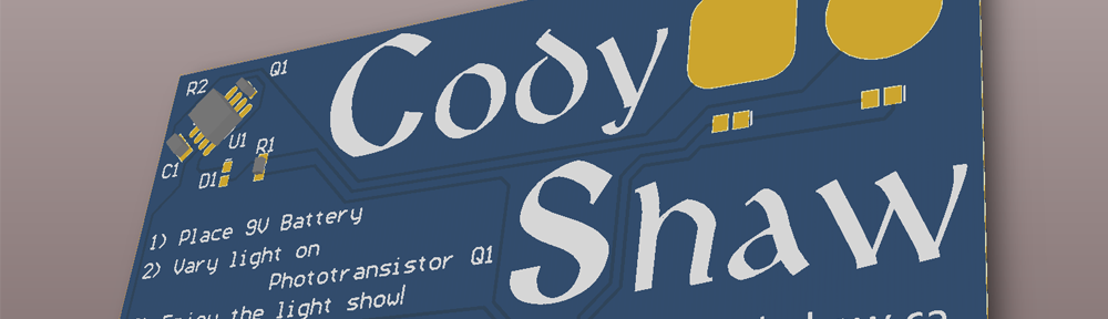
Cody
